Transformer Windings: Construction, Materials, Testing and Temperature Monitoring
- Published
- Author
- Komal Ganvir
- Reads
- 755
Transformer winding design balances voltage, current, insulation and cooling needs. Resistance meters and temperature indicators help assess winding condition and operation.
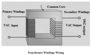
Transformer windings determine how a transformer handles voltage, current, insulation stress and heat. Their conductor material and geometry are chosen for the required electrical ratings and operating conditions, while resistance measurements and temperature indicators help assess their condition in service.
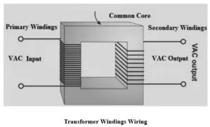
Electrical role and conductor choice
A transformer winding is made from insulated turns of copper or aluminium arranged around the core. The primary winding receives power from the input circuit; electromagnetic induction transfers energy to the secondary winding, which supplies the connected load. The number and arrangement of turns, conductor dimensions and insulation system are selected to meet the transformer’s voltage and current requirements.
Copper combines high electrical conductivity with good mechanical strength, which is why it is widely used in power and distribution transformers. Aluminium is lighter and generally less expensive, but its higher electrical resistivity means a larger conductor cross-section is usually needed for comparable electrical performance. Aluminium is also relatively easy to shape and manufacture. In either case, the finished transformer’s performance depends on conductor dimensions, insulation and cooling as well as the metal itself.
Winding geometries suit different duties
Construction varies with voltage rating, current capacity and application. The main arrangements include multi-layer helical, helical or spiral, disc, foil, cylindrical and cross-over windings, as well as disc and continuous disc designs. Aluminium windings are also commonly identified as a design category.
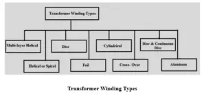
Helical and multi-layer arrangements
Multi-layer helical windings are used in high-voltage transformers, particularly at ratings of 110 kV and above. They comprise cylindrical layers connected in sequence. The outer layers may be shorter than the inner ones to produce a suitable capacitance distribution, an arrangement intended to improve behaviour under surge conditions.
Helical, or spiral, windings suit low-voltage, high-capacity transformers with high current and relatively few turns. The stated typical range is approximately 160 to 1000 kVA and 0.23 to 15 kV. Multiple parallel conductor strips can carry the current. A single helical winding has one layer following an axial, screw-like path; a double helical layout uses parallel conductors to help reduce circulating and eddy-current losses. In a disc-helical arrangement, conductor strips sit side by side in a radial pattern.
Disc, foil and cylindrical designs
Disc windings connect conductor discs in series. Each disc is formed from multiple turns of insulated conductor, and spacers keep adjacent discs apart while allowing cooling oil to circulate. The layout offers mechanical strength and flexibility in conductor and insulation placement, making it common in high-voltage transformers.
Foil windings use thin copper or aluminium sheets or strips wound spirally, with either one foil or several parallel foils depending on the design. They suit high-current applications and large-capacity transformers. Their compact construction also helps distribute current across the conductor width.
Cylindrical windings, commonly found in low-voltage and distribution transformers, place insulated round or rectangular conductors in layers around the core. Some designs use vertical spacers between layers to form oil ducts for cooling. The arrangement is straightforward and mechanically strong.
Cross-over and continuous disc construction
Small transformers may use cross-over windings divided into several coils. Insulating material separates the coils, reducing voltage differences between adjacent layers and helping limit insulation stress while supporting mechanical strength.
Large-capacity transformers commonly use disc or continuous disc windings: flat coils connected in series or parallel to meet the electrical design. Rectangular conductor strips are wound radially; pressboard spacers and insulating barriers separate sections, while oil ducts support cooling. The construction is mechanically strong, particularly against axial forces.
Resistance measurements reveal connection problems
A transformer winding resistance meter measures the electrical resistance of windings, joints and connections. Technicians take readings between appropriate winding terminals or phases, then compare them with expected values or earlier results. Differences can help identify loose or poor contacts, damaged connections and shorted turns.
These meters are designed for highly inductive equipment, including high-voltage power transformers. They can also be used to test generator and motor windings, inductors, tap changers, power cables and busbar connections.
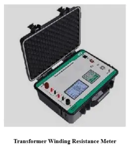
Temperature monitoring links load to protection
Winding temperature generally rises as transformer load increases, because electrical losses produce heat. A winding temperature indicator (WTI) monitors the estimated or measured winding temperature; an oil temperature indicator (OTI) monitors transformer oil temperature.
A WTI can connect to alarm, trip and cooling-control circuits. Traditional pointer-type units may show both the current winding temperature and the maximum recorded during operation. Preset temperature limits can trigger the corresponding control or protection function. This makes temperature indication part of the operating picture: it complements resistance checks by tracking thermal conditions rather than electrical continuity.
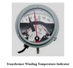
Design trade-offs and where windings are used
Well-designed windings couple the primary and secondary circuits, transfer energy through induction and can limit electrical losses. Their construction can be tailored to a wide range of voltage, current and power ratings. Mechanical strength and reliable operation depend on suitable conductor and insulation arrangements, manufacturing quality and maintenance.
Those requirements bring trade-offs. Winding manufacture calls for skilled labour and specialised equipment, while winding placement and insulation processes affect both electrical performance and production cost. Faults such as shorted turns or loose connections impair operation; high temperatures can shorten insulation life when cooling is inadequate.
Windings are used in step-up and step-down transformers for voltage conversion, distribution transformers, power transformers at generating stations and substations, and isolation transformers that separate circuits electrically. They also appear in power supplies, chargers and industrial transformers supplying machinery. The practical choice of winding geometry comes down to matching the electrical duty with insulation, mechanical strength and heat removal.