Raspberry Pi Pico 2 W LED Bar: MicroPython Control, Wi-Fi Commands and Current Measurements
- Published
- Author
- peppe8o
- Reads
- 578
A MicroPython library controls a 10-segment LED bar locally or over Wi-Fi; bench readings with 220 Ω resistors reached 31.6 mA for all segments.
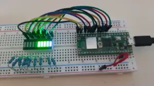
A 10-segment LED bar is a compact way to show a level or status, but its ten LEDs need individual current-limiting resistors and a clear mapping between display order and Pico GPIOs. The p8o_pico MicroPython library puts that mapping behind a LedBar class, with an optional WebLedBar class for browser commands on Wi-Fi-capable boards.
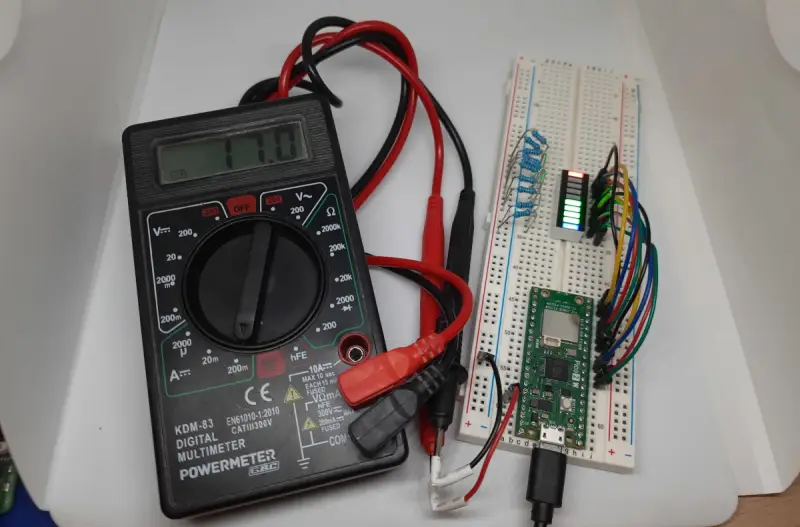
On a Raspberry Pi Pico 2 W, a bench setup with 220 Ω resistors drew 31.6 mA from the LED-bar supply branch with all segments lit. That figure is for the LEDs, not the combined load of the board, its Wi-Fi interface and the display. The measurements are indicative: the multimeter showed tenths of a milliamp, and some individual readings moved between adjacent displayed values.
Ten independent LEDs, one display
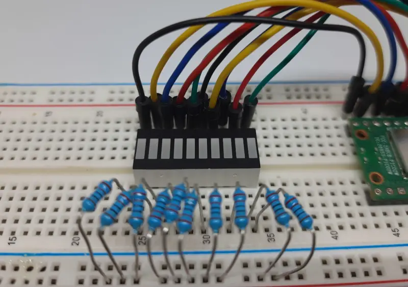
Each segment in the bar is a separate LED with an anode and a cathode. The package places the ten emitters in a row, but the physical pin arrangement and orientation can vary by manufacturer. Check the component’s pinout before wiring it; the label or a cut corner may help identify orientation, but neither is a substitute for the part’s documentation.
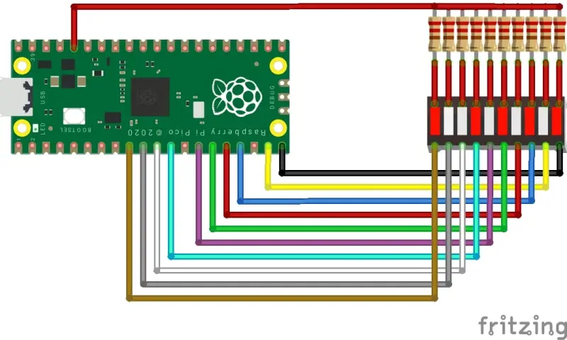
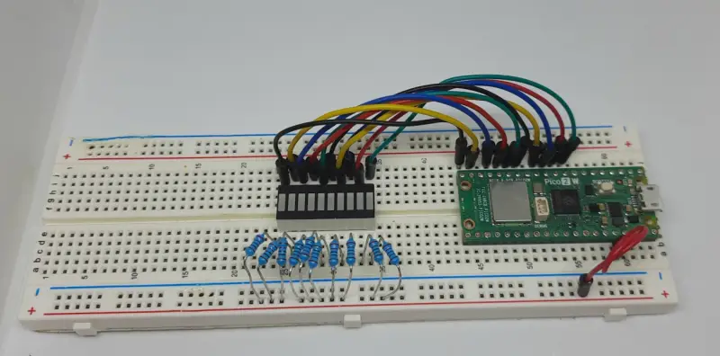
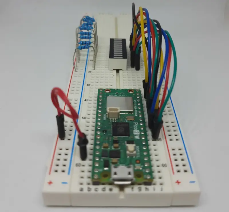
The circuit described here uses active-low control. Connect each anode to 3V3 and each cathode, through its own resistor, to a Pico GPIO. Driving a GPIO LOW turns its segment on; driving it HIGH turns the segment off. For active-high wiring, connect the cathodes to GND and route each anode through an individual resistor to a GPIO. Set the library’s common_anode parameter to match the actual circuit.

Use one current-limiting resistor per LED. A single resistor shared across several segments does not provide the same independent current control, and the LEDs should not be connected between the supply and GPIOs without resistors.
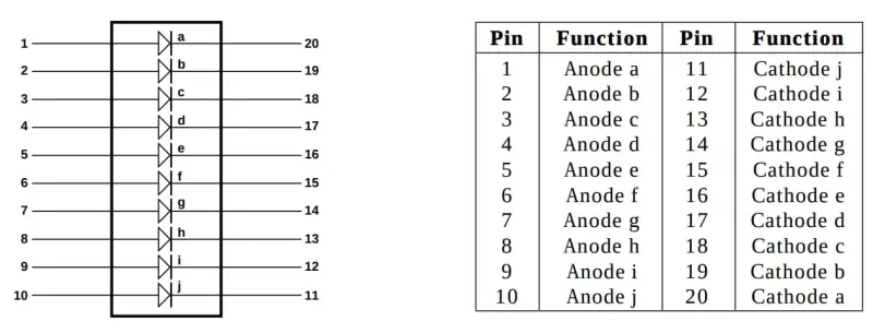
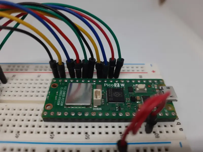
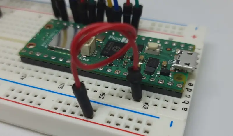
The tested layout assigns GP15 through GP6 to ten positions, in descending GPIO order. The first entry represents the highest logical position and the last entry the lowest. This software order describes the display pattern; it does not identify package pin numbers or LED colours.
| Pattern position | GPIO | Pico physical pin |
|---|---|---|
| 1 — highest | GP15 | 20 |
| 2 | GP14 | 19 |
| 3 | GP13 | 17 |
| 4 | GP12 | 16 |
| 5 | GP11 | 15 |
| 6 | GP10 | 14 |
| 7 | GP9 | 12 |
| 8 | GP8 | 11 |
| 9 | GP7 | 10 |
| 10 — lowest | GP6 | 9 |
The example uses a Raspberry Pi Pico or Pico 2 W, a 10-segment LED bar, ten resistors, a breadboard, jumper wires and a micro USB cable. The physical bar can indicate values such as tank level, battery charge or signal strength, provided the measured value is mapped to a suitable display pattern.

What the current readings show
The measurements were taken with a multimeter in current mode, placed in series between the Pico 2 W’s 3V3 supply and the bar’s shared anode connection. Each segment had a 220 Ω resistor. The segment numbers below mark the measurement sequence; they are not package pin numbers or GPIO identifiers.
| LED state | Measured current [mA] |
|---|---|
| All segments off | 0.0 |
| Segment 1 — blue | 2.3 |
| Segment 2 | 2.8 |
| Segment 3 | 2.7 |
| Segment 4 | 2.1 |
| Segment 5 | 2.9 |
| Segment 6 | 3.8 |
| Segment 7 | 4.6 |
| Segment 8 | 4.6 |
| Segment 9 | 4.5 |
| Segment 10 — red | 4.9 |
| All ten segments on | 31.6 |
The individual readings add to 35.2 mA, which is 3.6 mA above the simultaneous measurement. The difference is a useful reminder that the sum of separate readings is not necessarily the current observed when all segments operate together. With a one-decimal-place display and fluctuating individual values, treat these readings as a report of this setup rather than precision specifications for every bar.
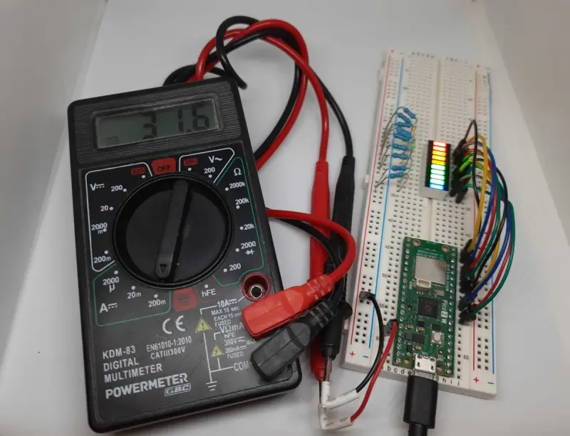
The reported 31.6 mA covers the LED-bar supply branch only. It excludes the Pico’s own consumption and its Wi-Fi activity. The measurement therefore helps characterize this display circuit, but it is not a complete board power figure.

Local control with MicroPython
The updated project uses the single-file p8o_pico library. Save p8o_pico.py on the Pico’s root directory, then save your own application as a separate file, such as led_bar_example.py. The library is available from the p8o_pico GitHub repository or as a raw Python file. Use Thonny to connect to the board and run the MicroPython program.
A minimal setup for the active-low circuit is:
from p8o_pico import LedBar

bar = LedBar(
    pins=[15, 14, 13, 12, 11, 10, 9, 8, 7, 6],
    common_anode=True
)

bar.led_bar_percentage(82)
The constructor takes ten GPIO numbers in logical display order and configures the outputs with the segments off. With the percentage call shown, eight segments light. The method uses completed 10% steps: a value of 5 lights none, 85 lights eight, and 100 lights all ten. Pass an integer from 0 to 100 without a percent sign; out-of-range values are rejected.

| Input | Segments on |
|---|---|
| 0 | 0 |
| 5 | 0 |
| 20 | 2 |
| 50 | 5 |
| 82 | 8 |
| 85 | 8 |
| 99 | 9 |
| 100 | 10 |
For direct pattern control, pass ten binary states to led_bar_show() in the same order as the GPIO list:
bar.led_bar_show([0, 0, 0, 0, 0, 1, 1, 1, 1, 1])This pattern leaves the first five positions off and lights the last five. To check which physical end corresponds to the first entry, try bar.led_bar_show([1, 0, 0, 0, 0, 0, 0, 0, 0, 0]). If that segment appears at the opposite end from the intended direction, reverse the GPIO list. Keep the polarity setting tied to the circuit wiring.
The bar.on() and bar.off() methods switch the full display on and off. A moving single-segment pattern can be run with bar.cycle(delay_ms=100, cycles=3). The delay and cycle count are optional; the default delay is 50 ms per segment. The method turns the segments off when it exits. It blocks the program until the requested cycles finish, so it suits a quick display check rather than an application that needs to keep doing other work.

Browser control on a Wi-Fi Pico
The standalone LedBar class does not import Wi-Fi modules, so local control is suitable for Pico models without wireless networking. On a Wi-Fi-capable Pico with compatible MicroPython firmware, WebLedBar adds a small HTTP server:
from p8o_pico import WebLedBar

bar = WebLedBar(
    pins=[15, 14, 13, 12, 11, 10, 9, 8, 7, 6],
    common_anode=True
)

bar.connect_wifi(
    ssid="YourHomeSSID",
    password="YourSSIDPassword",
    country="IT"
)

bar.serve()
Replace the example network details with your own. connect_wifi() returns the board’s IP address if the application needs to store it. Its optional verbose argument enables connection diagnostics, while reset controls whether the interface is disabled and re-enabled before connecting. Both default to False.
With the default server port of 80, the Thonny shell prints a listening address such as http://192.168.1.24. The port can be changed with serve(port=...), though the current listening message does not include a custom port. A browser request can set a percentage or a custom pattern:

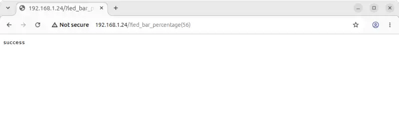
http://192.168.1.24/?led_bar_percentage(56)
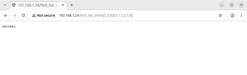
http://192.168.1.24/?led_bar_show([1,0,0,0,0,1,1,0,1,1])
A successful request returns plain-text success. An unsupported or malformed command returns HTTP 400 with the body error. The same requests can be sent from a computer on the reachable network using curl:
curl --globoff "http://192.168.1.24/?led_bar_percentage(82)"
curl --globoff "http://192.168.1.24/?led_bar_show([1,0,0,0,0,1,1,0,1,1])"
Quoting the complete URL protects the parentheses from shell interpretation; --globoff prevents curl from treating square brackets as a range.
Checks when something goes wrong
If the bar fills from the wrong end, reverse the GPIO list. If too many segments light, check that the physical circuit and common_anode setting agree: active-low wiring uses True, while active-high wiring uses False. An ImportError for p8o_pico usually means the file was not saved to the board, or its name gained an extra .txt suffix.

For a Wi-Fi timeout, enable diagnostics and use the connection timeout parameter, which defaults to 20 seconds:
bar.connect_wifi(
    ssid="YourHomeSSID",
    password="YourSSIDPassword",
    country="IT",
    timeout=20,
    verbose=True,
    reset=True
)
The diagnostic output reports the requested network name, elapsed connection time and network status without printing the password. On a successful connection it can also show network configuration and, when supported, signal strength. A timeout still raises an exception when verbose=False; suppressing messages does not suppress connection failures.
If a browser refuses the connection, compare its address with the current listening address in Thonny. The address can change between runs. Confirm that the script reached bar.serve() and is still running, use http://, and inspect the shell for exceptions. For curl syntax or range errors, quote the URL and include --globoff.
Keep the web interface on the local network
The HTTP example has no authentication or TLS. Anyone who can reach its port can change the LED state, so it is intended for a local-network demonstration and should not be exposed to the wider internet through port forwarding.
For a compact indicator, the project’s useful distinction is between the simple local driver and the optional network layer. The first works without Wi-Fi imports; the second offers direct browser or curl commands. In either case, the electrical details remain the same: verify the bar pinout, use one resistor per segment, and match software polarity to the circuit.