Prelta PS4395 and PS5395 Relays Add Adjustable Current Trips and Delays
- Published
- Author
- Saba Aafreen
- Reads
- 789
Prelta’s PS4395 monitors 1A to 100A AC, while the PS5395 covers bipolar DC ranges up to 100A, with configurable trip delays and three output types.
Prelta Systems’ PS4395 and PS5395 current-sensing protective relays let equipment designers set the current threshold that triggers an output and the delay before that output changes. The PS4395 monitors AC current; the PS5395 monitors bipolar DC. Adjustable trip points, delay choices and three output formats give engineers room to adapt current monitoring to motors, pumps, fans and heaters. The relays provide a signal for a control system to act on; they don’t, by themselves, define the response of the equipment.

The distinction between the models starts with the kind of current being monitored. The PS4395 covers AC currents from 1A to 100A at frequencies between 60Hz and 400Hz. The PS5395 is specified for bipolar DC and offers four selectable ranges: 1-10A, 3-30A, 6-60A or 10-100A. Range selection sets the scale on which the trip setting operates, so the model and range need to fit the installation’s expected current. A range that’s poorly matched to the load can make it harder to set a useful threshold.

Thresholds and delays shape the response
Both relays monitor current flowing through a conductor and change their output when the measured current crosses a configured level. The threshold can be set for an overcurrent condition, an undercurrent condition, or the direction of change an application needs to detect. That makes the devices useful for more than spotting overloads: a fall in current may also signal that a load has stopped drawing power as expected. The meaning of that change still depends on the machinery and its normal operating cycle.
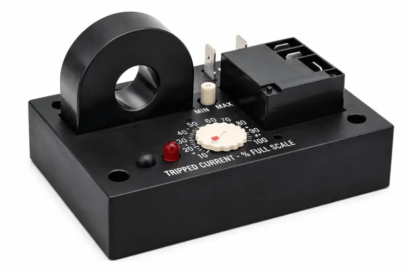
The delay setting determines how long the relay waits before switching its output after the current condition occurs. Prelta lists four on-delay choices: 0.5-6 seconds, 2-25 seconds, 0.1-1 second, or no delay. A delay can keep the output from reacting to a brief fluctuation, while no delay gives the fastest listed response. That’s a basic but consequential trade-off: filtering short variations can prevent nuisance signals, but waiting too long can postpone detection of a condition the control system needs to address.

Here’s the practical distinction: the threshold decides what counts as a meaningful current change, while the delay decides whether that change must persist before the output responds. In a motor or pump application, those settings can help distinguish a sustained operating condition from a short-lived variation. And yet, a relay setting can’t compensate for a poorly understood load profile. Engineers need to account for the machine’s normal behavior and the consequences of a delayed signal when choosing both values.
This is more significant than it looks: the relay’s response is only one part of a protection scheme. It supplies the switching signal, while the equipment’s control design determines what action follows. If you’re working in this space, the key question is whether the connected controls will interpret the selected output in a way that matches the intended response.

Three output formats
Each model offers three output options: a 20A single-pole double-throw (SPDT) relay, an opto-isolated NPN transistor, or an opto-isolated zero-crossing triac. The SPDT contact is rated for 20A normally open and 10A normally closed at 240V AC resistive load. Those ratings apply to the stated resistive-load conditions. They don’t establish suitability for every load type, so designers should check the load and the selected output’s specifications before integrating the relay.

The output choices serve different interface needs. A mechanical SPDT contact provides a changeover connection; the transistor and triac offer opto-isolated switching interfaces. That choice affects how the relay connects to the surrounding control circuit, not the current threshold or delay it monitors. The listed information doesn’t specify detailed drive requirements or additional load ratings for the transistor and triac, so those details need confirmation in the product documentation.
For the mechanical contact, the stated ratings also shouldn’t be read as a blanket rating for motor loads or other inductive loads. The information given specifies a resistive load, and the application’s switching demands need to be checked against the complete output specifications. A rating without its load conditions can tell only part of the story.
Internal sensing and larger conductors
Both relays include an internal current sensor with a half inch aperture. The monitored conductor passes through this opening, which creates a straightforward installation constraint: the conductor has to fit. This may affect how the device is mounted and routed, especially where existing wiring leaves limited clearance. Prelta says remote transformers can be used for larger conductors, allowing the relay to sense current without routing the conductor through its built-in opening.
That option changes the physical arrangement, so it’s part of the installation decision rather than a detail to leave until commissioning. The available information doesn’t give further transformer specifications or wiring instructions. Engineers should check the product documentation to confirm the applicable components and installation requirements.
Choosing the relay for the application
For engineers comparing the pair, the main selection points are current type, operating range, conductor size, required delay and output interface. The PS4395 is the AC option across 1A to 100A and 60Hz to 400Hz; the PS5395 is the bipolar DC option with four selectable ranges, including a top range of 10-100A. Both offer adjustable trip behavior and the same three output formats. The model names alone won’t tell you whether a particular installation fits: the current envelope and control interface have to be checked.
What this means for you is that selection starts with the load and the signal the control system needs, then works through the relay’s stated range, delay and output limits. The aperture or remote-transformer arrangement also needs to fit the wiring plan. For a practical design review, check each of those conditions against the intended installation and verify the remaining output and wiring details in Prelta’s product documentation. A careful match matters.